


- Offer
- Offer
- System types
- System KAN-therm ultraLINE
- System KAN-therm Push
- System KAN-therm ultraPRESS
- System KAN-therm PP
- System KAN-therm PP Green
- System KAN-therm Steel
- System KAN-therm Inox
- System KAN-therm Steel Sprinkler
- System KAN-therm Inox Sprinkler
- System KAN-therm Groove
- System KAN-therm Copper
- System KAN-therm Tacker
- System KAN-therm Profil
- System KAN-therm Rail
- System KAN-therm TBS
- System KAN-therm WALL - the wet method
- System KAN-therm WALL - the dry method
- System KAN-therm Football
- KAN-therm InoxFlow
- KAN-therm Cabinets Slim & Slim+
- Installation types
- Heating and cooling installations
- Cold and hot tap water systems
- Underfloor heating and cooling systems
- Wall heating and cooling systems
- External surfaces heating and cooling systems
- Firefighting sprinkler system
- Technological and industrial systems
- Form-inquiry
- KAN-therm water supply distribution systems
- Examples of KAN-System mixer tap fixture branches
- Calculators
- KAN-therm SMART & BASIC+ Automation Systems
- New products in offer
- KAN-term with a new QB certificate.
- Download
- Guarantee of quality
- Reference objects
- About us
- Contact


1. Pipe Cutting
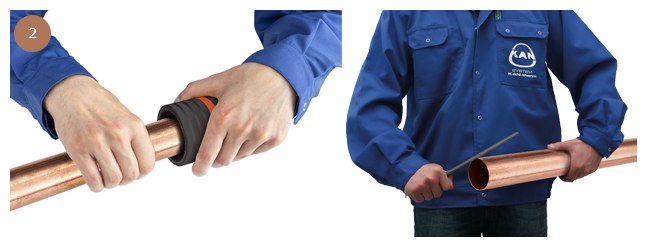
2. Chamfering of Pipe Edges
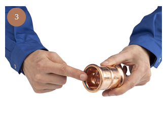
3. Control
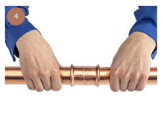
4. Installing the Pipe and Fitting
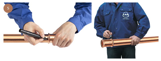
5. Marking the Insertion Depth of a Pipe into a Fitting
7. Pressing of Connections with 42–108 mm Diameters. Preparation of Jaws.
8. Once the jaws have been correctly positioned on the fitting, they are ready for connection to the crimping tool.
9. Connecting Crimping Tool to Jaws
10. Pressing
Connecting Technology
Installation of System KAN-therm Copper is based on the ‘press’ connection technique, using the ‘M’ crimping profile. It allows for:
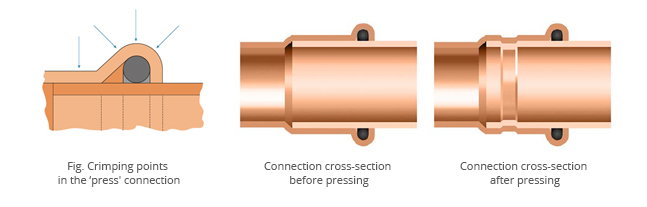
- achieving a three point O-ring compression to ensure that the seal is properly deformed and adheres to the pipe surface,
- complete closure of the space in which the O-ring is seated by pressing the edge of the fitting to the surface of the pipe. This prevents the penetration of dirt inside connection and provides natural mechanical protection for the seal and mechanical reinforcement of the joint,
- inspection of the seal condition due to the shape of the O-ring seat near the edge of the fitting,
Assembly of Connections
1. Pipe Cutting
Cut the pipe perpendicularly to its axis using a roll cutter (the cut must be full, without breaking off of the cut pipe sections). It is allowed to use other tools provided that the cutting is perpendicular and that the cut edges are not damaged in the form of breaks, material losses and other deformations of the pipe cross-section. It is not permitted to use tools that may generate significant amounts of heat, e.g. torches, angle grinders, etc.
2. Chamfering of Pipe Edges
Using a handheld chamfer (for 76.1–108 diameters: half-round file), chamfer the tip of the cut pipe inside and out and remove any swarf that may damage the O-ring during installation.
3. Control
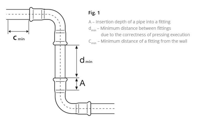
Before installation, the presence of O-rings in the fitting should be visually checked for damage to the fitting, as well as for any contamination (swarf or other sharp objects) that may cause damage to O-rings during pipe insertion phase. It is also necessary to make sure that the distance between adjacent fittings is not less than the permissible dmin value.min.
4. Installing the Pipe and Fitting
Before pressing, the pipe should be inserted axially into the coupling to the specified depth (light rotary motion is permitted). The use of oils, greases and fats to facilitate the insertion of the pipe is prohibited (water or aqueous soap solution is permitted — recommended for pressure testing with compressed air).
5. Marking the Insertion Depth of a Pipe into a Fitting
In order to achieve the proper strength of the connection, it is necessary to maintain the appropriate depth A of the pipe insertion into the fitting. After inserting the pipe into the fitting as far as it goes, mark the required insertion length on the pipe (or fitting with a bare end) with a marker. After pressing, the marking must still be visible right next to the edge of the fitting. Special templates are also used to determine the insertion depth without necessity of matching with the fitting. In case of simultaneous assembly of multiple connections (on the principle of inserting pipes into fittings), before the pressing of each subsequent connection, the insertion depth should be checked by observing the marks made with a marker on the pipe.
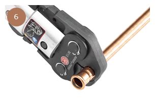
6. Pressing of Connections
Before starting the pressing process, check the efficiency of the tools. The use of crimping tools and jaws supplied as part of System KAN-therm Copper is recommended.
Always select the right jaw size for the diameter of the joint. The jaws should be placed on the fitting in such a way that the groove made in the jaw exactly covers the area where the O-ring is seated in the fitting (convex part of the fitting). Once the crimping tool has been started, the pressing process is automatic and cannot be stopped. If, for some reason, the pressing process is interrupted, the connection must be disassembled (cut out) and a new one must be made in the correct way. If the installer has crimping tools and jaws not supplied with System KAN-therm Copper, the feasibility of using them should be consulted with KAN-therm company.
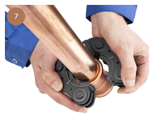
7. Pressing of Connections with 42–108 mm Diameters. Preparation of Jaws.
For larger diameters (42 mm, 54 mm, 66.7 mm, 76.1 mm, 88.9 mm, 108 mm), special four-part snap-on jaws are used.
The unfolded jaw should be placed on the fitting. The jaws have a special groove in which the hump of the fitting should fit (the location of the O-ring gasket).
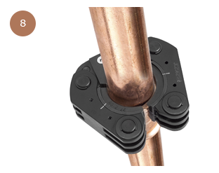
8. Once the jaws have been correctly positioned on the fitting, they are ready for connection to the crimping tool.
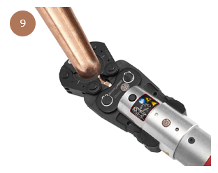
9. Connecting Crimping Tool to Jaws
The crimping tool with a pre-mounted, suitable adapter must be connected to the jaws. It is essential to ensure that the crimping tool is connected to the jaws in accordance with the instructions supplied with the tool.
The crimping tool connected to the jaws may be started to press the connection fully.
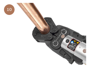
10. Pressing
Once the crimping tool has been started, the pressing process cannot be stopped. If, for some reason, the pressing process is interrupted, the connection must be disassembled (cut out) and a new one must be made in the correct way. After pressing, the crimping tool automatically returns to its original position. The arms of the crimping tool (adapter) must then be pulled out of the jaws. In order to remove the jaws from the fitting, it must be unlocked again (in the case of 42–108 mm diameters) and then disassembled. Jaws should be stored in suitcases in locked position.
Mounting Distances
Copper pipes approved for use with the System KAN-therm Copper
| Ø [mm] | A [mm] | dmin [mm] |
| 12 | 17 | 10 |
| 15 | 20 | 10 |
| 18 | 20 | 10 |
| 18 | 20 | 10 |
| 22 | 21 | 10 |
| 28 | 23 | 10 |
| 35 | 26 | 10 |
| 42 | 30 | 20 |
| 54 | 35 | 20 |
| 66,7 | 50 | 30 |
| 76,1 | 50 | 55 |
| 88,9 | 64 | 65 |
| 108 | 64 | 80 |